TESTEMONIAL
MAAT
Structural Engineer (FEUP) and PhD Student (FAUP)
Nowadays, it seems possible to design a building with any shape or form. The sophisticated and powerful numerical methods, combined with refined user-friendly interfaces, have sometimes led designers to think that, be it engineers or architects, a building of any form might be built as soon as we make a digital representation of it.
With computer aided design (CAD) tools, engineers and architects have switched from the drawing board to a more productive and efficient digital interface. CNC machines promise a highly efficient production chain, like a factory assembly line. Therefore, the designers have the tools, technologies and techniques that allow exploring, testing and erecting buildings that would not have been feasible in the past.
This is a paradox, in the sense that technology should be easing processes but, in fact, under the motto that the “computer does it all”, promotes the complication of processes and steers engineering even further from the conceptual process. The advice of Frei Otto is here to warn us that the computer is merely a tool and that the concepts and ideas are what should govern the design process of a project, despite all the potential that technology might bring.
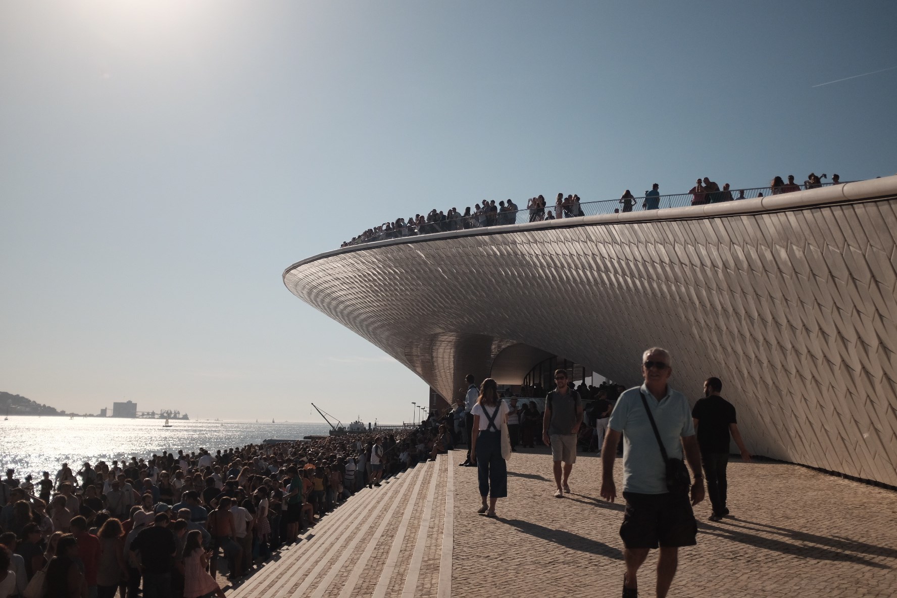
The EDP Museum of Art, Architecture and Technology (MAAT), designed by Amanda Levete Architects, is a building where several of these issues have been brought together. The complex shell form of the MAAT, completely generated in nurbs at Rhinoceros, reflected the intention of the architects to renew the public's access to the river Tagus, thus re-establishing the connection between the city and the water that was lost due to the extensive port of Lisbon and railway infrastructures. The building blends in with its surroundings, creating an artificial topography that allows people to walk on it - on top, underneath or through it – and reflects a clear intention of permeability between inside and outside.
The challenge of the complex curved-shape of the MAAT is evident: how can we tame such an “animal” from a structural point of view? Structure is almost always of primary concern in a project and the most basic relation between form and materiality is made in dialogue with gravity.
The English engineers had already made a preliminary study in which they created some massive steel frames with tapered sections, that would chop the building from top down. This was an expensive solution, since it was very heavy and it demanded sophisticated cutting machines that are usually used for aeronautical and auto industries. Additionally, the presence of the huge frames would severely restrict any exhibition project that one would want to implement.
When Afaconsult joined the project, the goals of its intervention were clear: to define an economic and feasible solution, without overriding deadlines and budget, while combining all the engineering services and structure in an integrated design approach – where the project is not the sum of parts and in which every service contributes to explore the potential of the other, replying to the ideas and expectations of the architects.
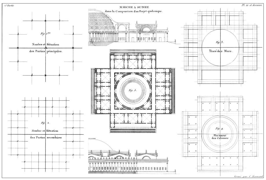
The structural design of the MAAT started with the idea of making the structure disappear and followed the usual engineering guidelines: look for points of support, define grids, hierarchies, main and secondary axis, and sketch some sections of the rooftop to define materials, weights and loads.
This way of proceeding is deeply rooted on the métier of engineers and one of its roots lies in Durand’s architecture classes at the École Polytechnique, in the early 19th Century. The classes of Durand were assembled in a time when scientific knowledge was very basic and the first modern engineers were in fact architects that designed large scale buildings and infrastructures. They had the goal of providing future engineers with a systematic method of composition to design buildings that still resonates with the structural design methods that engineers apply nowadays.
Presently, engineers no longer design the form of a building and even the notions of space have changed – in Durand’s period it was contained, axial and ordered; today it can also be open, fluid and organic. These lessons of Durand, although potentially dated, can be reinterpreted from a contemporary perspective and, above all, they might prove valuable as a process of rationalisation and systematisation of the design process.
In the MAAT, the definition of the main axis started with the main space. It was obvious that this would be the most important exhibition room – the oval space – with over 800m2. At the centre of this space the main axis were defined, vertical and horizontal. From this point, axis were tested – spaced 2.5m, 5m and 7.5m – and we concluded that a grid, spaced every 5m, was the most well-adjusted, in a balance between cost of primary and secondary structure. With the main grid set, the main vertical supports were defined – the reinforced concrete walls. In a dialogue with the architects, some adjustments were made to ensure that the grid would work.
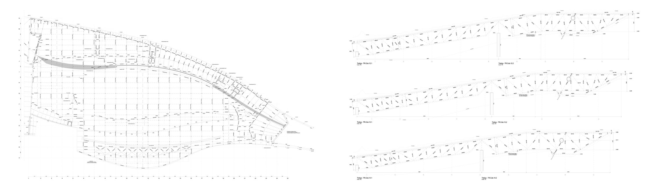
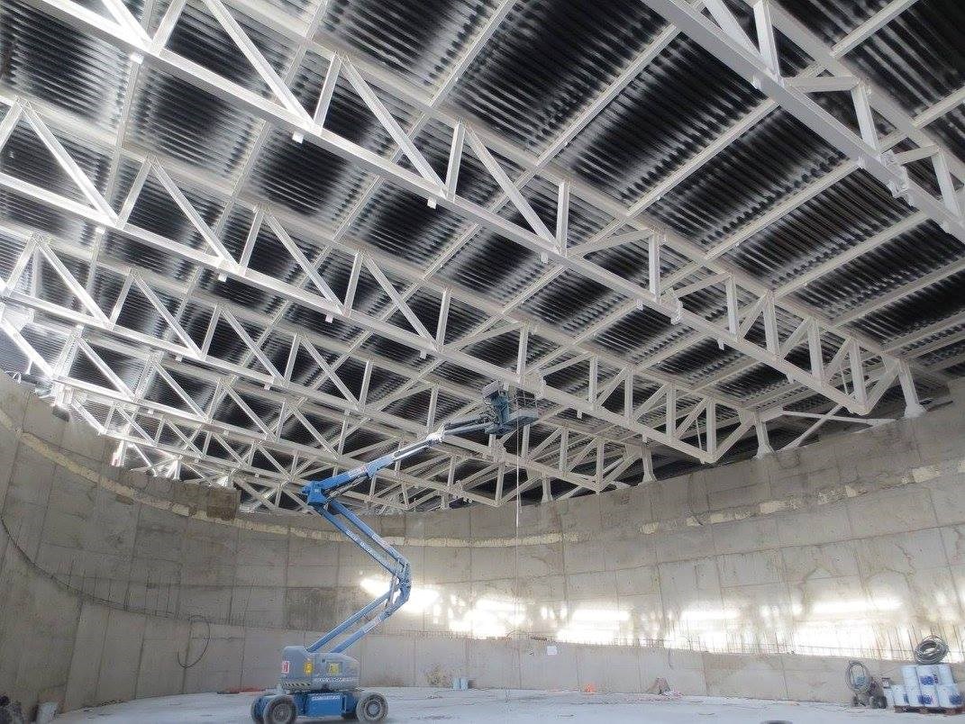
For the horizontal elements of the big rooftop – the beam – trussed steel-concrete beams were employed (with H-shaped cross-section and steel deck) on the direction perpendicular to the river. The solution, in addition to being more economical than a beam section, ensured a desired flexibility for the cross-over and integration of the large HVAC ducts.
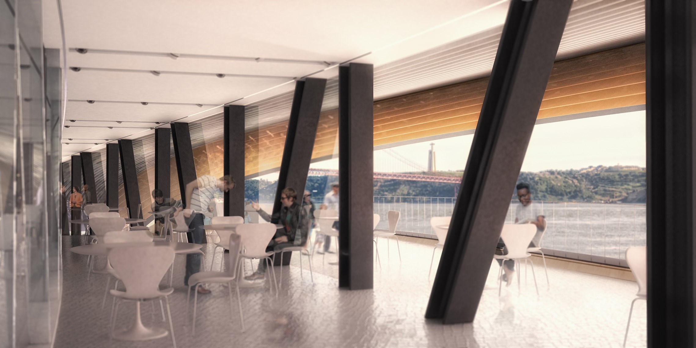
With the trusses resting on the walls of the oval room, it was necessary to ensure support at the south of the room. The most obvious (and economical) solution would be to support the trusses on columns that would stretch to the foundations. However, this would jeopardise the fluidity of the adjacent spaces of the oval room – columns always want to order space – and so these columns had to disappear.
The first alternative was a tall Pratt truss, with a height of 7m and a total span of 70m, that would suspend the slab of the cafeteria and the entrance ramp while supporting the roof trusses.
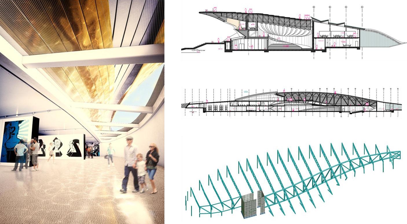
This was a solution that offered security, flexibility and cost control, but it was not satisfying. Who would want to have a coffee in the bar and have their view framed by struts and diagonals with 30cm of thickness? For the designers this was incoherent and, despite being a competent answer, the initial goal of making the structure “disappear” was not being achieved.
The answer to this problem was once again found in the history of structural engineering. In 1864, the German civil engineer Karl Culmann began to publish the monography Die Graphische Statik, where he exposed a graphical method (based on projective geometry) that established a relation between the polygon of forces and the funicular polygon. This is a design method centred on drawing, based on Monge’s tradition at the École Polytechnique where descriptive geometry and mathematical analysis were centred at the engineering design process, that was seeking a synthesis in geometry between representation and analysis.
Graphical statics is a structural method that establishes a synthesis between form and structure, in a process in which the structure is being calculated while it is being drawn. Despite being used for a short period – it was less competitive on hyperstatic structures – the examples of structures that were designed with this method, such as the bridges of Théophile Seyrig in Porto, show the potential of this (almost) forgotten method of structural engineering.
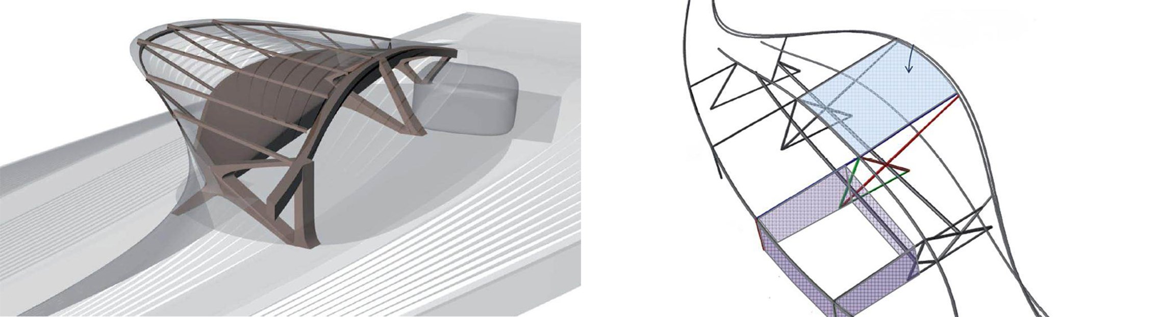
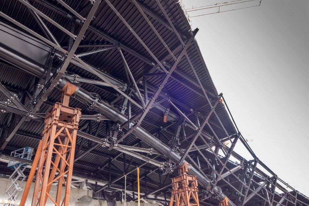
After a few sketches, it became clear that it was possible to replace the tall Pratt steel truss with a big arch with a span of over 70m and a total height of 9.5m, in a plane 30º from the vertical. With some sketches, to control the insertion, and more rigorously in Autocad, the preliminary design of an antifunicular arch with 3 fixed points was made. It would be a big arch, with a cross-section of over 70cm of diameter that would hold forces of 35MN (3500 tonnes). The architects had no doubts that this would be the solution, and the surrounding of the buttresses and the geometry of the façade were redesigned to make sure it was possible to integrate the antifunicular arch.
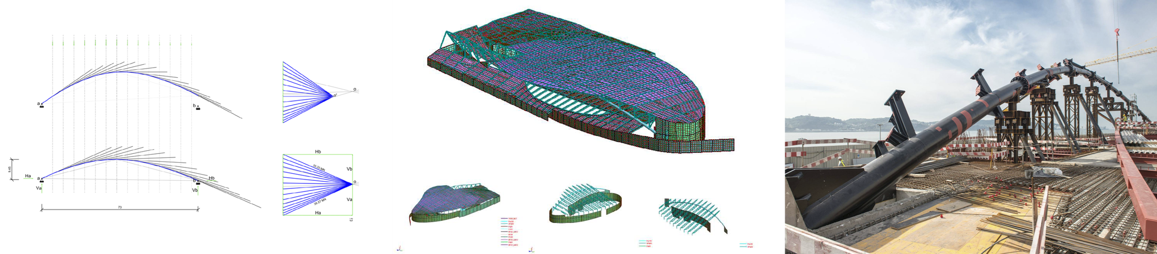
Nonetheless, it was difficult with the large deformations of the rooftop that the arch was supporting, due to the hyperstatic nature of this system, which would require endless calculations and very complex computational models – something that should be avoided. The solution was then to release all supports other than those strictly needed, resulting in isostatic trusses – like the ones the engineers of iron architecture used to design in the 19th Century. In this way, it was possible to control its behaviour, optimise cross-sections and the huge deformations could be easily corrected with precamber.

In contemporary engineering practice it is evident that engineers, as in the past, need to have a common language with architects. Culmann’s motto “drawing is the language of engineers” remains valid. In sketching, technical drawings or advanced parametric modelling, it is the medium, in the course of projects, where the intersection between architecture and engineering happens.
Old methods from the past, such as Durand’s method of systematisation through the use of the grid and the hierarchisation of elements allowed us to rationally tame a very complex geometry, while deconstructing a complex form in its most evident and simple elements. Graphical statics, long gone from the curricula of the majority of engineering degrees, allowed in the MAAT’s project, to replace a big truss by an elegant arch that was simpler to design, while at the same time being an efficient and economical solution.
This proves that old methods, which in their simplicity might seem neglectful in contemporary practices or even in a didactic use, still hold their ground and might help us to design better structures and architectural spaces. ◊